Skip to content
 Filling density is the single production variable that most directly determines how a plush toy feels — and therefore how customers perceive its quality. A product with correct filling density feels substantial, holds its shape, and communicates premium quality through the hands before the customer has consciously evaluated any other attribute. A product with insufficient density feels limp, compresses too easily, and creates a quality impression that no amount of excellent fabric or skilled embroidery can compensate for.
Despite this centrality to commercial quality, filling density is one of the production variables most commonly managed inadequately — either through imprecise specification that leaves density to the operator’s judgment, through absent or insufficient in-process monitoring that allows density to drift undetected across a long production run, or through the kind of cost-driven density reduction that appears nowhere on a quotation but shows up clearly in every product that reaches a customer.
The reason filling density is so often managed inadequately is that it is invisible to most quality assessment methods. A product with 15 percent less filling than the correct specification looks identical to a correctly filled product in product photography. It may pass a visual inspection conducted without physical handling. It only reveals itself through compression — through the immediate tactile experience of picking up the product and feeling whether it resists compression the way a quality product should.
This guide provides the complete framework for filling density control in plush toy production — from establishing the correct target density before sampling begins, through the calibration and monitoring systems that maintain it across a production run, to the verification methods that confirm it across a completed batch.
What Is Filling Density and Why Does It Determine So Much of a Plush Toy’s Commercial Value?
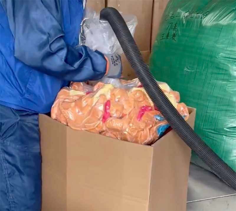
Filling density in plush toys refers to the amount of filling material — typically PP cotton fiber fill — packed into a defined volume of the product’s interior. It is most practically measured and controlled through unit weight — the total weight of filling in a completed unit — which provides an objective, measurable proxy for the density that the customer experiences as product firmness and shape retention.
Filling density determines commercial value through its effect on the three product characteristics that customers evaluate most directly when handling a plush toy: firmness (how much the product resists compression when squeezed), shape retention (how fully the product returns to its intended form after being compressed), and weight perception (how substantial the product feels relative to its size).
Here is a framework for understanding how filling density variations affect each commercial quality dimension:
| Filling Density Level | Customer Experience | Commercial Consequence | Review Sentiment |
|---|---|---|---|
| Significantly under-filled (-25%+) | Limp, deflated, collapses under light pressure | Returns, one-star reviews citing “cheap stuffing” | Very negative |
| Under-filled (-10–25%) | Noticeably soft, inadequate shape retention | Quality complaints, brand perception damage | Negative |
| Slightly under-filled (-5–10%) | Marginally soft — perceptible to quality-sensitive customers | Occasional complaints, lower repeat purchase | Slightly negative |
| Correctly filled (±5%) | Firm, responsive, shape-retaining | Customer satisfaction, positive review sentiment | Positive |
| Slightly over-filled (+5–15%) | Very firm, almost rigid | May feel unnatural — customer preference varies | Neutral to slightly negative |
| Significantly over-filled (+15%+) | Rigid, seams under stress | Seam failure risk, unnatural feel | Negative from different direction |
The Business Case for Density Control Investment
The commercial case for investing in filling density control is straightforward when the analysis extends beyond unit production cost to total commercial economics. A 10 percent density reduction saves approximately 10 percent of filling material cost — for a standard small plush toy, this is typically $0.05 to $0.20 per unit. The commercial consequence of that density reduction — in returns, negative reviews, and reduced repeat purchase rates — is systematically larger than this per-unit saving across any commercially meaningful production volume.
For e-commerce products specifically, where every one-star review containing the words “poorly stuffed” or “cheap feeling” affects the listing’s conversion rate for every subsequent customer who reads it, density control is a brand equity investment with returns that compound over the product’s commercial life.
How Is the Target Filling Density Established for a New Plush Product?

Target filling density for a new product cannot be accurately determined from a formula or a general guideline — because the correct density depends on the specific product’s size, shape, construction, fabric characteristics, and intended use. The correct approach is empirical: building and evaluating physical samples at multiple density levels to identify the density at which the product achieves the intended quality standard.
The target filling density establishment process follows a structured sampling approach that produces an objective, commercially validated density specification before production is authorized.
Here is the complete target density establishment process:
| Process Step | Activity | Output | Decision Point |
|---|---|---|---|
| Initial density estimation | Factory estimates probable density range based on product type and size | Starting weight range for samples | Factory recommendation |
| Multi-density sample production | Produce counter samples at minimum three density levels: estimated low, target, high | Three physical samples with documented weights | For evaluation |
| Compression and recovery evaluation | Each sample compressed to 60% of height, released — recovery measured at 30 minutes, 2 hours, 24 hours | Recovery data for each density level | Establish minimum acceptable recovery |
| Shape retention evaluation | Each sample evaluated for shape accuracy against design reference | Shape assessment for each density level | Identify visual quality threshold |
| Firmness evaluation | Each sample handled and evaluated for customer-appropriate firmness | Subjective firmness assessment at each level | Identify commercial quality floor |
| Threshold identification | Identify lowest density level that meets all three quality standards | Minimum acceptable density established | Cost-quality optimization point |
| Target weight specification | Set target weight above minimum, with tolerance above minimum | Target weight and tolerance for production | Production specification |
| Counter sample approval | Counter sample at target density approved as production reference | Approved counter sample with documented weight | Production authorization baseline |
Why Three Density Levels Are Required
The three-level sampling approach — low, target, high — is more expensive than single-density sampling but produces information that is not available from a single sample. The low-density sample identifies whether the product is usable at a lower density than initially estimated — which may reveal cost optimization opportunities. The high-density sample reveals whether over-filling creates problems — rigid feel, seam stress, unnatural shape — that set the upper bound on the acceptable density range. And the comparison between all three levels gives the buyer and factory a concrete, physical demonstration of the quality difference that density variation creates — which is the most effective way to align both parties on the importance of density control before production begins.
This shared physical understanding of the density-quality relationship is itself a valuable outcome of the three-level sampling process. A factory whose team has seen side-by-side samples at different densities understands concretely what the specification is trying to achieve — which produces better density control than a specification number alone communicates.
How Is Filling Density Specified in Technical Documentation?

Filling density specification in technical documentation transforms the empirically established target density from a physical sample understanding into a written, measurable standard that can be applied consistently by production operators, quality control personnel, and external auditors without requiring them to have personally evaluated the samples.
A complete filling density specification contains four elements: the target weight, the acceptable weight tolerance, the functional density standard, and a reference to the physical approved counter sample that serves as the definitive quality reference.
Here is a complete filling density specification framework:
| Specification Element | What It Defines | Format | Example |
|---|---|---|---|
| Target fill weight | The nominal weight of filling in each completed unit | Grams with decimal precision | “Target fill weight: 185g” |
| Weight tolerance | The acceptable range above and below target | ±percentage of target | “Tolerance: ±8% (170g–200g)” |
| Compression recovery standard | The functional density requirement expressed as recovery | Recovery % at defined time after compression | “Compress to 60% height under 2kg load — recover to minimum 88% within 2 hours” |
| Firmness reference | The tactile firmness standard | Reference to approved counter sample | “Firmness consistent with approved counter sample — available at QC station” |
| Filling material specification | The specific filling material the density applies to | Grade and type designation | “Premium high-loft PP cotton — Grade A (see material specification)” |
| Measurement method | How density will be measured in production | Scale specification and measurement point | “Weigh completed, stuffed, closed unit before packaging — OHAUS precision scale ±1g” |
The Tolerance Setting Decision
The tolerance setting — the acceptable range above and below the target weight — is a specification decision that involves balancing production efficiency against quality consistency. A tighter tolerance (±5%) requires more precise equipment calibration and more frequent monitoring corrections — but produces more consistent density across the production run. A wider tolerance (±12%) allows more production variation — which reduces the frequency of corrective calibration events but produces a wider density spread in finished products.
For most commercial plush products, a tolerance of ±8 to 10 percent of target weight represents a reasonable balance — tight enough to prevent density variation that customers can detect through normal handling, while wide enough to accommodate the natural variation of a well-maintained production process.
The critical constraint on tolerance setting is that the lower bound of the tolerance — the target weight minus the tolerance — must still meet the compression recovery standard established during sampling. If the low-density sample at the tolerance’s lower bound fails the recovery standard, the tolerance is too wide and must be tightened — even if the production process prefers wider tolerance.
Documenting the Measurement Method
The measurement method specification — exactly how density will be measured and at what production stage — is as important as the target weight itself, because the same product measured at different production stages produces different weights. A unit measured before closing seam is lighter than the same unit measured after closing (if accessories or labels are added after stuffing). A unit measured at room temperature behaves differently under compression than the same unit at a different temperature.
Specifying the exact measurement point — “weigh after closing seam, before label application” — and the measurement equipment — “precision scale, 0.1g resolution” — ensures that the specification number is meaningful across all measurement contexts and that production monitoring, IPQC, and FQC measurements are comparable to each other and to the specification.
How Does Stuffing Equipment Selection and Calibration Affect Density Consistency?

Stuffing equipment is the primary mechanical tool that delivers filling into the product — and its selection, setup, and calibration are the most directly controllable determinants of density consistency in industrial plush toy production. The right equipment, correctly calibrated and actively maintained, is the foundation of consistent density across a production run. The wrong equipment, or correctly specified equipment that is poorly calibrated or inadequately maintained, produces density variation that no amount of operator skill or quality monitoring can fully compensate for.
Here is a framework for understanding how equipment choices and calibration practices affect density consistency:
| Equipment Factor | Effect on Density Consistency | Professional Standard | Common Failure Mode |
|---|---|---|---|
| Machine type — air stuffing vs conveyor | Air stuffing offers better density control through pressure adjustment | Match machine type to product complexity | Wrong machine type for product requiring complex distribution |
| Machine capacity vs product size | Machine sized for product volume produces more consistent output | Machine capacity matched to product fill volume | Oversized machine for small products — poor density control |
| Air pressure settings | Pressure determines fill rate and density | Calibrate to target output before each production run | Pressure drift from temperature or wear changes output |
| Feed rate settings | Feed rate determines volume per unit time | Calibrate to target weight output | Feed rate drift from mechanical wear |
| Nozzle size and placement | Affects distribution within product | Nozzle matched to stuffing opening size and product geometry | Wrong nozzle creates distribution problems in complex areas |
| Calibration frequency | How often settings are verified | Calibrate before each run, verify after warm-up | Calibration done once at run start, never rechecked |
| Machine maintenance | Effect of wear on output consistency | Regular professional servicing | Deferred maintenance allows output to drift progressively |
The Calibration Verification Sequence
Machine calibration is not a one-time event at the start of a production run — it is a sequence of verification steps that must be completed before production authorization is given and repeated at defined intervals during the run.
The professional calibration sequence for a stuffing machine involves:
Step 1 — Cold calibration: Set the machine to the target output parameters based on the production specification. Produce five test units and weigh each. Calculate average weight and variation.
Step 2 — Warm-up period: Allow the machine to run at operating conditions for a defined warm-up period — typically 10 to 20 minutes — before measuring production output for calibration purposes. Machine output characteristics change significantly as operating temperature stabilizes.
Step 3 — Warm calibration verification: Produce five test units after warm-up and weigh each. Compare to cold calibration output. If warm output has shifted from cold calibration, recalibrate settings to achieve target output at operating temperature.
Step 4 — Production authorization: Authorize production start only after warm calibration verification confirms target output within tolerance.
Step 5 — Documented baseline: Record the calibrated settings, warm-up output weights, and calibration time as the production run baseline for comparison with subsequent monitoring measurements.
This five-step sequence takes 30 to 40 minutes before production starts — a time investment that prevents the density variation problems that result from starting production without verified warm-calibration confirmation.
Equipment Limitations for Complex Products
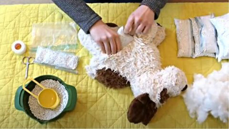
Not all plush products are well-suited to fully automated stuffing. Products with complex geometries — small appendages, narrow limb sections, deep facial recesses — may have areas that stuffing machines cannot reach effectively. In these areas, manual hand-stuffing supplements the machine filling.
The transition from machine-delivered to hand-delivered filling within the same product creates a density control challenge: machine sections can be weight-verified consistently, but hand-stuffed sections rely on operator judgment. Managing this challenge requires explicit density guidance for hand-stuffed sections — typically a firmness reference comparison against the approved counter sample — and supervisor spot-checking of hand-stuffed section quality at defined intervals.
How Do Operator Technique and Workflow Design Affect Filling Density Outcomes?
Operator technique and workflow design affect filling density outcomes through their influence on the consistency of filling distribution within the product — which is distinct from the consistency of total fill weight. A product can meet its weight specification while having filling distributed unevenly — concentrated in the body with underfilled limbs, or dense at the top with insufficient filling at the bottom — producing a product that technically passes a weight check but fails the shape and firmness standard that weight measurement is supposed to confirm.
Operator technique affects density distribution through the speed and sequence of filling operations, the method of filling complex areas, the assessment of distribution before the closing seam is sewn, and the final shape confirmation that is the last opportunity to identify distribution problems before the product is permanently sealed.
Here is a framework for operator technique standards that support consistent density distribution:
| Technique Standard | What It Controls | Quality Dimension Protected | Training Requirement |
|---|---|---|---|
| Fill sequence — body before appendages | Ensures body receives full fill before appendages consume capacity | Body density | Written sequence in work instructions |
| Appendage fill verification | Confirms each appendage is filled before proceeding | Limb density consistency | Firmness check technique training |
| Facial area fill technique | Maintains correct fill distribution around embedded features | Feature area density | Specific technique for feature areas |
| Pre-closing distribution check | Verifies distribution matches counter sample before seam | Overall distribution | Visual comparison technique training |
| Closing seam tension management | Prevents closing seam from distorting final fill distribution | Shape of closed unit | Seam technique specification |
| Post-closing shape assessment | Confirms final product form before quality handover | Overall shape against counter sample | Counter sample comparison training |
The Fill Sequence as a Quality Tool
The fill sequence — the order in which different areas of the product are stuffed — is one of the most important and least commonly documented operator technique standards. Without a defined sequence, operators stuff in whatever order is most convenient, producing variable distribution that depends on individual operator habit rather than on what the product requires.
A professionally designed fill sequence accounts for three factors: the gravity-driven settling behavior of filling material (fill from the top down so gravity helps distribute filling toward the bottom), the access constraints of the product’s geometry (fill areas that are hardest to access first, while access is unobstructed by surrounding filling), and the structural requirements of complex products (fill compartments or sections sequentially to maintain clean internal structure).
For simple products — basic bears, bunnies, standard character shapes — the fill sequence may be straightforward and quickly trainable. For complex character products with multiple distinct body areas, the sequence specification may be several steps long and require initial supervised practice to ensure operators are executing it correctly.
The Pre-Closing Distribution Check
The pre-closing distribution check — a visual and tactile assessment of filling distribution conducted before the closing seam is sewn — is the most high-value operator-conducted quality check in the entire stuffing process. At this point, the product is fully stuffed and the distribution is established, but the closing seam has not yet been sewn, making redistribution a simple manual operation.
Any filling distribution problem identified at this check can be corrected in seconds — by redistributing filling manually and verifying the correction before sealing. The same problem, identified after the closing seam is sewn, requires seam opening, redistribution, and resealing — significantly more labor-intensive. And the same problem, reaching the customer, generates a complaint or return.
Training operators to conduct a meaningful pre-closing check — not a perfunctory glance but an actual comparison against the counter sample and a firmness check at key areas — requires both technique training and the consistent availability of the counter sample at the stuffing workstation for comparison.
How Is Filling Density Monitored and Controlled During a Production Run?

In-process filling density monitoring is the continuous surveillance system that detects density drift before it accumulates into commercially significant quality failures. Without this monitoring, density drift from machine setting changes, filling material variation between bales, and operator technique changes develops invisibly throughout the production run — producing a batch where later-produced units may differ significantly from earlier ones, and where the average density across the run may be within specification while individual units span a wide range.
In-process density monitoring operates through three complementary monitoring systems that together provide comprehensive coverage of the density variation risks that arise during a production run.
Here is the complete in-process density monitoring framework:
| Monitoring System | What It Detects | Frequency | Method | Action Trigger |
|---|---|---|---|---|
| Weight monitoring — primary | Density drift from machine settings or filling material | Every 150–200 units | Scale measurement of finished units | Any reading outside target tolerance |
| Shape and firmness spot check | Distribution problems not captured by weight | Every 200–300 units | Physical comparison to counter sample | Any visible shape deviation or firmness inconsistency |
| Pre-closing distribution check | Distribution problems before they are sealed | Every 50–100 units | Visual and tactile before closing seam | Any visible distribution inconsistency |
| Bale transition monitoring | Filling quality change at bale changeover | At each bale transition | Physical comparison of new bale to approved reference | Any visible loft or quality difference |
| Shift-transition density check | Density after machine reset for new shift | At each shift start | Weight measurement of first five units | Any weight outside tolerance at shift start |
The Weight Monitoring Interval Decision
The weight monitoring interval — how frequently fill weight is checked during the production run — involves a trade-off between monitoring cost and the number of units that may be produced with an uncorrected density deviation before it is detected.
A 150-unit interval means that when density drifts outside tolerance, up to 150 units may be produced before the drift is detected. This number is acceptable for most commercial applications because 150 units represents a rework scope that can be managed within the production schedule. A 500-unit interval means up to 500 potentially non-conforming units before detection — which may be too large a rework scope for some projects. A 50-unit interval provides earlier detection but adds significant QC time overhead that may not be justified unless the product has unusually tight density requirements.
The appropriate interval should be calibrated to the production’s drift history — machines and filling materials with well-documented stability can be monitored at longer intervals; new equipment, new filling suppliers, or products with tight tolerances warrant shorter intervals.
Responding to Weight Monitoring Deviations
When a weight measurement falls outside the specified tolerance, the immediate response sequence matters as much as the monitoring itself. An inadequate response — simply adjusting the machine and continuing production — may address the measured deviation without identifying whether earlier units produced before the deviation was detected also fall outside tolerance.
The professional deviation response sequence:
Step 1 — Stop production on the affected operation immediately upon detecting a deviation.
Step 2 — Assess scope — how many units have been produced since the last passing weight check? These units are potentially non-conforming and must be set aside for 100 percent reinspection.
Step 3 — Identify cause — is the deviation from machine drift (most common), filling material quality change at bale transition, or operator technique change? Each cause has a different corrective action.
Step 4 — Implement correction — recalibrate the machine (if machine drift), assess the new bale against the reference (if bale transition), or retrain the operator (if technique change).
Step 5 — Verify correction — produce five test units at the corrected settings and weigh each. Confirm all five are within tolerance before resuming production.
Step 6 — Document — record the deviation, scope, cause, correction, and verification results in the IPQC log.
This response sequence limits the scope of potentially non-conforming production to the interval between the last passing check and the failing check — typically 150 to 200 units — and creates a documented record that demonstrates how the deviation was managed.
How Does Final Inspection Verify Filling Density Across a Completed Batch?

Final inspection for filling density is the last quality gate before shipment — the systematic verification that the completed, packed production batch meets the density specification across the AQL-sampled unit population. Unlike earlier quality checks that catch problems while correction is still efficient, FQC density verification confirms whether the in-process controls succeeded or whether any density failures reached the completed batch.
FQC density verification uses weight measurement as the primary objective tool — because weight measurement produces a number that can be directly compared to the specification without subjective judgment — supplemented by physical firmness and shape assessment that captures distribution quality that weight measurement alone cannot verify.
Here is a complete FQC filling density verification protocol:
| FQC Check | What Is Verified | AQL Application | Method | Pass/Fail Criterion |
|---|---|---|---|---|
| Fill weight — AQL sample | Unit weight within tolerance across batch | AQL 2.5 — major defect | Weigh each sampled unit | All measurements within target ±tolerance |
| Shape assessment — visual | Shape consistent with counter sample | AQL 2.5 — major defect | Visual comparison under consistent lighting | No visible shape deviation from counter sample |
| Surface firmness consistency | No perceptible soft or hard spots | AQL 2.5 — major defect | Hand assessment of sampled units | No identifiable distribution inconsistency |
| Compression recovery — spot test | Recovery after compression | Non-AQL — spot test 5 units | Compress to 60%, measure recovery at 2 hours | Minimum 85% recovery |
| Limb and appendage density | Correct fill in smaller areas | AQL 4.0 — minor to major | Hand squeeze of appendages | No visibly underfilled appendages |
Third-Party Inspection for Density Verification
For high-value orders, orders with tight density specifications, or orders where density compliance is a marketed product attribute — weighted plush where the specific weight is part of the product positioning, premium character plush where shape integrity is a core brand value — commissioning third-party inspection that explicitly includes filling density verification provides independent, documented evidence of density compliance.
Third-party inspection protocol for density should specify: weight measurement on a defined unit sample size; the target weight and tolerance against which measurements are assessed; the measurement equipment specification; and any shape or firmness assessment requirements. SGS, Bureau Veritas, and Intertek can execute this protocol as part of a standard pre-shipment inspection visit.
Including filling density in the third-party inspection scope adds minimal time and cost to the inspection — typically 15 to 20 minutes for weight measurement across a standard AQL sample — while providing objective, independently documented evidence that the batch meets the density specification. For products where density is a primary quality differentiator, this investment is commercially justified.
How Can Buyers Specify and Verify Filling Density Standards in Their Supplier Relationships?

Filling density standards can be built into supplier relationships through contractual specification, process requirements, and verification rights that collectively transform density from an assumed production variable into a defined, monitored, and verified quality obligation.
Here is a complete framework for building filling density requirements into supplier relationships:
Contractual Specification Elements
| Contractual Element | What to Include | Commercial Purpose |
|---|---|---|
| Target fill weight | Specific weight in grams with decimal | Creates objective measurement basis |
| Tolerance range | ±percentage with explicit lower and upper bounds | Defines acceptable production range |
| Compression recovery standard | Recovery percentage at defined time after compression | Defines functional quality threshold |
| Measurement method | Specific scale, measurement point, unit | Ensures consistent measurement across contexts |
| Counter sample retention | Factory must retain physical approved counter sample | Maintains production reference standard |
| Filling substitution prohibition | Any filling grade change requires buyer approval | Prevents unauthorized density reduction through grade change |
| IPQC weight monitoring requirement | Factory must maintain weight log at defined intervals | Creates accountability for monitoring |
| Documentation availability | Weight logs available to buyer on request | Creates visibility into production compliance |
Pre-Production Verification Actions
| Verification Action | What It Confirms | Timing |
|---|---|---|
| Counter sample weight confirmation | Target weight achievable in production environment | At counter sample review |
| Compression recovery test | Counter sample meets functional density standard | At counter sample review |
| Equipment calibration documentation | Machine calibrated to target output before production | Before production authorization |
| Filling material IQC confirmation | Approved filling material confirmed for production run | Before production authorization |
During Production Verification Actions
| Verification Action | What It Confirms | Timing |
|---|---|---|
| First-off weight report request | Production density confirmed at run start | Production day 1 |
| IPQC weight log review | Density consistency maintained during run | At 50% and 100% completion |
| Mid-production physical sample request | Physical density verification at production scale | Optional — at buyer’s discretion |
Pre-Shipment Verification Actions
| Verification Action | What It Confirms | Timing |
|---|---|---|
| FQC weight measurement report review | Batch density distribution within specification | Before payment authorization |
| Third-party inspection weight check | Independent density verification | Before shipment authorization |
| Shape assessment in inspection | Distribution quality in finished batch | As part of third-party scope |
The Most Effective Single Verification Action
Of all the verification actions available, the most commercially effective single action for buyers who cannot implement the full framework immediately is requesting and reviewing the IPQC weight log from the production run before authorizing the balance payment. The weight log provides two critical pieces of information: whether density monitoring was conducted throughout the production run, and whether any deviations were detected and corrected.
A complete, consistent weight log showing measurements at defined intervals with all readings within specification provides strong evidence that density was actively managed throughout the run. A log with gaps, irregular intervals, or recorded deviations without documented corrective actions reveals density management inadequacies that should be investigated before shipment is approved.
At Kinwin, filling density control is built into our standard production process at every stage described in this guide — from the three-level density sampling approach we use to establish the correct target density for new products, through the machine calibration verification sequence we complete before every production run, to the IPQC weight monitoring log we maintain throughout production and share with clients as a standard component of our production documentation.
For clients where filling density is a primary quality differentiator — premium character plush, therapeutic or comfort products, any product where customer reviews on firmness and shape retention are commercially important — we work with clients at the design and specification stage to establish density standards through physical sampling rather than assumptions, and we document density management throughout the production run to provide verifiable evidence that the standard was maintained.
If you want to understand how our filling density control process would apply to your specific product, we would be glad to walk through it with you.
Reach out to our team at [email protected] or visit kinwintoys.com to start that conversation.
Conclusion
Filling density control is not a single quality check conducted at the end of production — it is a continuous management discipline that spans every stage from the initial density specification established through structured sampling, through the equipment calibration and operator technique standards that maintain density during production, to the in-process monitoring and final inspection verification that confirm density compliance across the completed batch.
The commercial case for this investment is clear: density control is the most directly connected production variable to the customer experience dimensions — firmness, shape, substance — that drive the quality reviews and repeat purchase rates that determine long-term brand value. Every dollar invested in density control systems consistently returns more in prevented quality failures than it costs in production overhead.
Buyers who build explicit density specifications, process requirements, and verification rights into their supplier relationships take control of the production variable that most directly determines their customers’ quality experience — and that control is the foundation of the consistent product quality that builds enduring brand equity in the plush toy market.
FAQ
Q1: How should buyers handle a situation where the factory’s quoted unit cost is based on a filling density that is lower than the target density established during sampling — should they accept the lower density to meet the budget, or insist on the specified density at higher cost?
This situation requires an explicit decision rather than a default acceptance of the lower density. The right decision depends on whether the lower density falls above or below the minimum acceptable density established during sampling — the compression recovery threshold below which the product fails the functional quality standard. If the factory’s proposed density still meets the recovery standard — if it is within the acceptable range but at the lower end — the decision is a commercial trade-off between cost savings and quality margin above the minimum. If the proposed density falls below the recovery standard — producing a product that fails the compression recovery test — accepting it creates a commercial liability through customer quality complaints that will cost more than the unit price saving. The density calibration work done during sampling specifically addresses this question by establishing the minimum acceptable density empirically rather than through judgment. That minimum is the non-negotiable floor for density specification, regardless of cost pressure.
Q2: Is it possible to accurately assess filling density in a finished product without destructive testing — and if so, what methods are most reliable?
Yes — filling density in finished plush products can be assessed without destructive testing through three non-destructive methods that together provide a reliable density assessment. Weight measurement is the most objective method — weighing the completed unit on a precision scale and comparing the result to the target weight specification. Shape and firmness assessment — physically compressing the product and evaluating how firmly it resists compression and how fully it recovers — provides a functional density evaluation that correlates directly with customer experience. And compression recovery testing — compressing the product to a defined percentage of its height under a standard load, then measuring the height at defined intervals after release — provides a quantified functional assessment. Together, these three methods provide comprehensive filling density evidence without requiring the product to be opened. Weight measurement and compression recovery are the most objective and most suitable for documentation purposes; shape and firmness assessment provides the direct customer-experience proxy that weight measurement alone cannot fully capture.
Q3: How does the correct target filling density change when the same design is produced in multiple sizes — for example, small (25cm), medium (35cm), and large (50cm) versions of the same character?
Target filling density does not scale linearly with product size — and assuming it does is one of the most common specification errors in multi-size plush development. The correct approach is to establish the target density independently for each size through the same three-level sampling process described in this guide, because the relationship between fill weight, product volume, and perceived firmness changes as size increases.
A larger product has more volume relative to its surface area — which means that achieving the same surface firmness requires proportionally more filling per unit volume in a larger product than in a smaller one. The practical implication is that fill weight increases faster than product size: a product that is twice the volume of a smaller version typically requires more than twice the fill weight to achieve equivalent firmness perception.
Additionally, larger products are more susceptible to gravity-induced filling migration — the tendency of filling to settle toward the lowest point — which means that density control requirements become more stringent as size increases. For a large plush product displayed standing on a shelf, the filling in the upper body must be dense enough to resist gravity-driven migration toward the lower body over the display period — a requirement that the weight specification alone does not fully capture, and that may require internal structure additions for very large products.
Q4: What is the most reliable way to verify that the filling density in a production run matches the density in the approved counter sample, given that the counter sample is a physical object that cannot be weighed against every production unit?
The counter sample serves as the reference standard for visual and tactile density assessment — the physical object against which shape and firmness comparisons are made in IPQC and FQC. Its function is to anchor the subjective quality assessments that weight measurement alone cannot capture. The weight measurement system serves as the objective, quantifiable control mechanism that can be applied to every inspected unit without requiring the counter sample to be present for every check.
The verification system works as follows: the counter sample is weighed when it is approved, and its weight becomes the target weight specification. Every subsequent weight measurement — in pre-production calibration, in IPQC monitoring, in FQC inspection — is compared to this target weight. When weight measurements fall within the specified tolerance of the counter sample weight, the density is confirmed as consistent with the approved standard. When a weight measurement falls outside tolerance, the physical comparison to the counter sample provides the reference for assessing how the density deviation has affected shape and firmness — confirming whether the deviation is commercially significant or within the acceptable range of variation.
This two-system approach — objective weight measurement for systematic monitoring plus physical counter sample comparison for quality reference — provides more reliable density verification than either system alone.
Q5: How should filling density requirements be communicated and managed when working with a factory for the first time, compared to an established relationship where density standards are already understood?
For a first-time factory relationship, filling density requirements should be communicated through explicit, complete specification — target weight, tolerance, compression recovery standard, measurement method, and physical reference sample — combined with a pre-production calibration verification requirement and a request for IPQC weight log documentation from the production run. This level of specificity compensates for the absence of shared production history and ensures that density requirements are understood objectively rather than assumed.
For an established relationship where the factory has demonstrated consistent density control across multiple production runs, some of this specificity can be streamlined — the factory already has the approved counter sample, understands the weight specification, and has demonstrated the calibration discipline to maintain it. The verification requirements can be simplified accordingly: confirming that the same specification applies to the reorder, reviewing the IPQC weight log as a standard communication, and spot-checking FQC weight measurements rather than requiring comprehensive density documentation. The key is that the streamlining is earned through demonstrated performance history — not granted as a default assumption of a long-term relationship, since performance history is what justifies the reduced verification overhead.